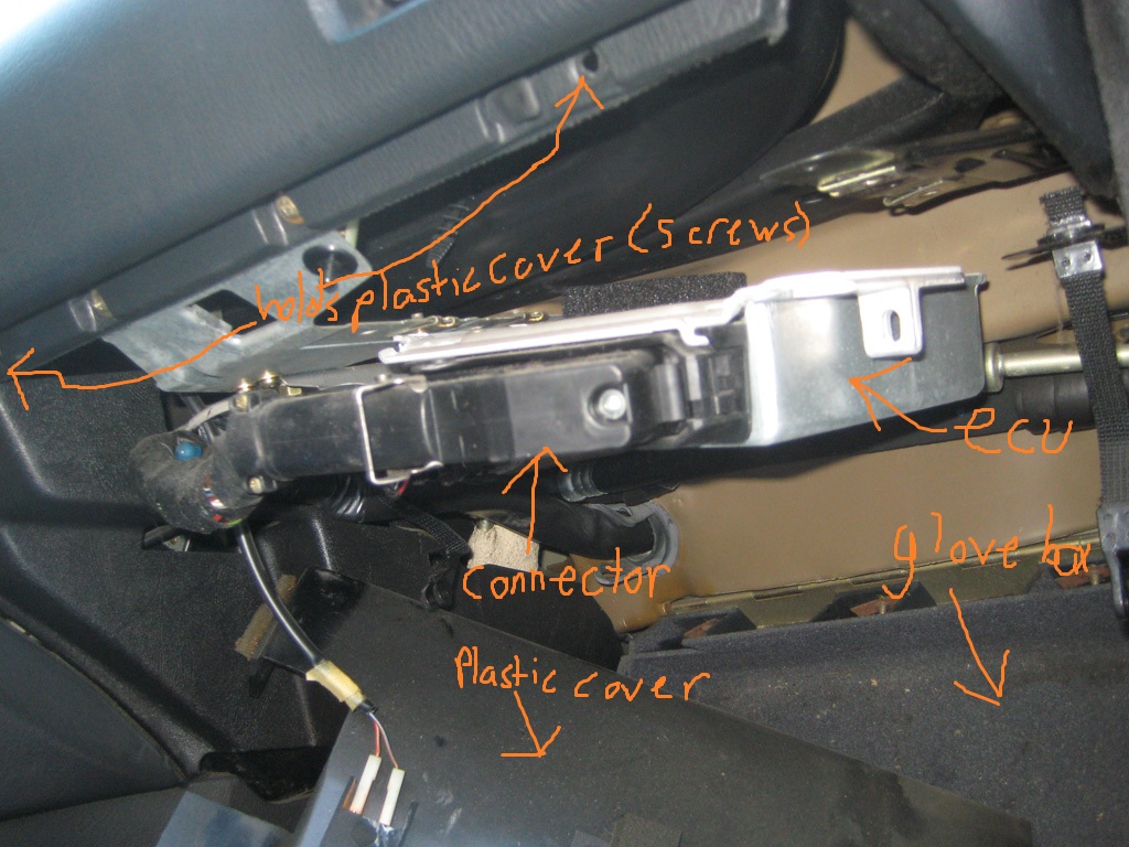
Where and how to access ECU: I have tried to illustrate where and how to access the ECU, it is in the glove box compartment. To access it open your glove box and undo the two screws holding the plastic cover that is at the "ceiling" of the glove box compartment, under there you will find the ECU and the Connector.
Interesting fact: The 153 Motronic 1.1 ECU is directly swappable (without any modification or otherwise) with all motronic 1.3 ECU's. The Grey label 173 is the most popular of the 1.3 ecu's, mainly because of its availability. Generally speaking there is no advantages to running one 1.3 ECU over another. The differences between the 1.1 and 1.3 apart from software updates is that the 1.3 uses only 1 board within the ECU whereas the 1.1 uses two boards. Having less boards means less failure points. Some people have claimed to have better idle with the 1.3 ECU's although I haven't noticed such improvements. As I have covered in another article the main benefit to the 1.3 ECU's is that they are able to store engine fault codes and you do not need a scanner to access them, all you need to do is preform a stomp test. Click "this" to access the stomp test page.

The Motronic 1.0 ECU (325, 325e)
| Pin | Function | Pin | Function | Image |
|---|---|---|---|---|
| 1 | Ignition coil output | 19 | Ground |  |
| 2 | Idle switch | 20 | Main relay | |
| 3 | WOT switch | 21 | Tachometer | |
| 4 | Cranking signal | 22 | AFM Temp sensor | |
| 5 | Ground/Crank PosS Gnd | 23 | Inlet Air Temp/Crank SpS Gnd | |
| 6 | AFM ground | 24 | O2 sensor signal * | |
| 7 | AFM signal | 25 | Crank position sensor 1 | |
| 8 | Crank speed sensor 1 | 26 | Crank position sensor 2 | |
| 9 | AFM supply | 27 | Crank speed sensor 2 | |
| 10 | Auto only special | 28 | Water Pressure switch | |
| 11 | Fuel consumption gauge | 29 | A/C switch (if installed) | |
| 12 | 30 | +Inlet Air Temp | ||
| 13 | Water Temp | 31 | ||
| 14 | Injector output cyl 3&4 | 32 | ||
| 15 | Injector output cyl 1&2 | 33 | ICV pulse | |
| 16 | Ground | 34 | ICV pulse | |
| 17 | Ground | 35 | Injector ground | |
| 18 |
Motronic 1.1 (325i, 325is, 325ix) Green label 153 ECU.
| Pin | Function | Pin | Function | Pin | Function | Image |
|---|---|---|---|---|---|---|
| 1 | Timing Control – to coil and O2 sensor | 20 | 38 |  | ||
| 2 | Ground | 21 | 39 | Programming voltage – Diagnostic Plug | ||
| 3 | Fuel pump relay control | 22 | Idle speed control | 40 | A/C on input | |
| 4 | Idle speed control | 23 | O2 sensor heater | 41 | ||
| 5 | Evaporative purge valve | 24 | Ground | 42 | Park/ neutral input (auto only) | |
| 6 | Engine Speed output- to instrument cluster | 25 | 43 | |||
| 7 | AFM input – pin 2 | 26 | AFM common- ground pin 4 | 44 | AFM air inlet temp- pin 1 | |
| 8 | Cylinder ID sensor input | 27 | Start input- to ignition switch and coil | 45 | Coolant Temp input | |
| 9 | 28 | O2 input | 46 | |||
| 10 | O2 sensor ground | 29 | 47 | Engine speed input | ||
| 11 | 30 | 48 | Engine speed input | |||
| 12 | AFM reference output- pin 3 | 31 | Cylinder ID sensor input | 49 | ||
| 13 | RXO – diagnostic plug | 32 | Econometer | 50 | ||
| 14 | Ground | 33 | 51 | |||
| 15 | Check engine light – to cluster | 34 | 52 | Closed throttle input – pin 1 | ||
| 16 | Injectors 1,3,5 | 35 | 53 | WOT input – pin 3Note: TPS pin 2 is ground | ||
| 17 | Injectors 2,4,6 | 36 | Main relay | 54 | ||
| 18 | Power input main relay | 37 | Power input – to main relay | 55 | TXD – diagnostic plug | |
| 19 | Ground |
Motronic 1.3 (325i, 325is, 325ix) later model 173 grey label ECU and others (351, 380, 382, 524, 525, 526)
| Pin | Colour | Function | Pin | Colour | Function | Pin | Colour | Function | Image |
|---|---|---|---|---|---|---|---|---|---|
| 1 | BK | Timing Control – to coil and O2 sensor | 20 | 38 | ABS and OBC cutoff for Injectors |  | |||
| 2 | BR | Ground | 21 | 39 | GN/BU | Programming voltage – Diagnostic Plug | |||
| 3 | BR/GN | Fuel pump relay control | 22 | WT/GN | Idle speed Close control | 40 | BK/GY | A/C low pressure cutoff | |
| 4 | WT/YL | Idle speed control | 23 | BR/GR | O2 sensor heater | 41 | VI/GY | A/C On input | |
| 5 | BR | Evaporative purge valve | 24 | BR | Ground | 42 | RD/BU | Park/ neutral input (auto only) | |
| 6 | BK | Tachometer | 25 | 43 | |||||
| 7 | GY/YL | AFM input – pin 2 | 26 | GY/BU | AFM common- ground pin 4 | 44 | GY/VI | AFM air inlet temp- pin 1 | |
| 8 | BL | Cylinder ID sensor input | 27 | GN | Start input- to ignition switch and coil from OBC | 45 | BR/RD | Coolant Temp input | |
| 9 | 28 | BK | O2 input | 46 | |||||
| 10 | YL | O2 sensor ground | 29 | BK/WT | Vehicle Speed input frominstrument cluster | 47 | BL | Engine speed input | |
| 11 | 30 | 48 | YL | Engine speed input | |||||
| 12 | GY/WT | AFM reference output- pin 3 | 31 | YL | Cylinder ID sensor input | 49 | |||
| 13 | WT/YL | RXO – diagnostic plug | 32 | WT/BL | Econometer | 50 | ABS Deceleration Fuel Cut-Off Overide | ||
| 14 | BR | Injector Ground | 33 | 51 | Auto Kick-Down Switch input | ||||
| 15 | GY | Check engine light – to cluster | 34 | 52 | BR/BL | Closed throttle input – pin 1 | |||
| 16 | BR/WT | Injectors 1,3,5 | 35 | 53 | BR/BL | WOT input – pin 3Note: TPS pin 2 is ground | |||
| 17 | BR/YL | Injectors 2,4,6 | 36 | BR | Main relay output | 54 | Automatic Transmission Torque Converter Lock-up Switch | ||
| 18 | RD | Constant 12V fromBattery | 37 | RD/BU | Switched power from main relay | 55 | WT/VI | TXD – diagnostic plug | |
| 19 | BR/OR | Main Ground |
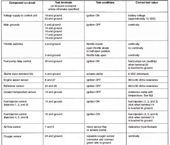
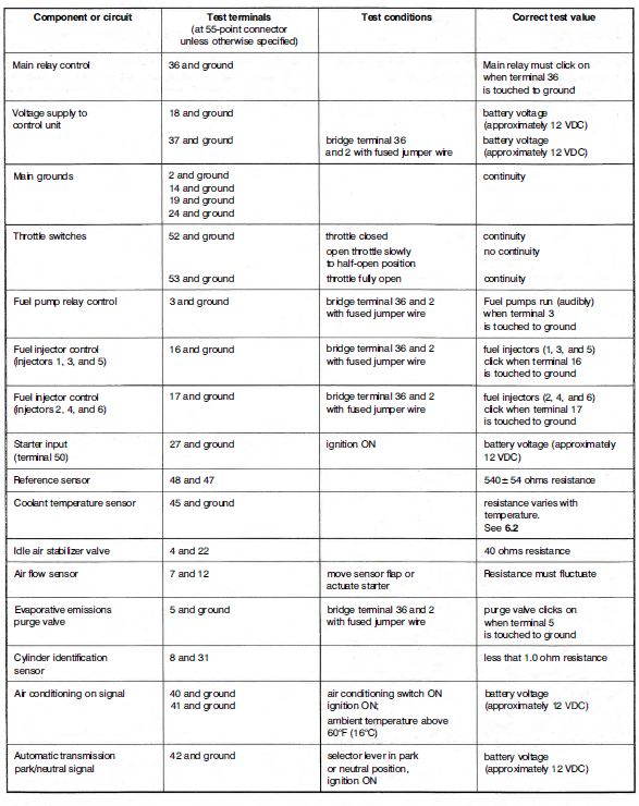
ECU electrical tests (at the connector)
35 pin (325, 325e)

55pin (325i, 325is, 325ix)
 List of 6 cylinder E30 ECU's
325i/is/iX
E30
M20/B25 (170hp)
87-91
0 261 200 153
Bosch Motronic M1.1
325i/is/iX
E30
M20/B25 (170hp)
87-91
0 261 200 173
Bosch Motronic M1.3
325i/is/iX
E30
M20/B25 (170hp)
87-91
0 261 200 351
Bosch Motronic M1.3
325i/is/iX
E30
M20/B25 (170hp)
87-91
0 261 200 380
Bosch Motronic M1.3
325i/is/iX
E30
M20/B25 (170hp)
87-91
0 261 200 382
Bosch Motronic M1.3
325i/is/iX
E30
M20/B25 (170hp)
87-91
0 261 200 524
Bosch Motronic M1.3
325i/is/iX
E30
M20/B25 (170hp)
87-91
0 261 200 525
Bosch Motronic M1.3
325i/is/iX
E30
M20/B25 (170hp)
87-91
0 261 200 526
Bosch Motronic M1.3
325e/es
E30
M20/B27 (122hp)
9/84-12/86
0 261 200 027
Bosch Motronic Basic M1.0
325e/es
E30
M20/B27 (127hp)
1/87-9/87
0 261 200 154
Bosch Motronic M1.1
This entry was posted on October 27, 2012 at 9:14 pm and is filed under Do it Yourself. You can follow any responses to this entry through the RSS 2.0 feed.
Posted by: trippettetha424.blogspot.com
Source: https://www.rtsauto.com/ecu-pinout-and-electrical-tests-e30/
